As part of an ongoing project, I wanted to see how low I could get the power consumption of Arduinos to go. The reason is as follows. When getting back into Arduinos a few months ago, I wanted to try a telemetry project of some sort, collecting data remotely and sending it back. Ideally, the idea would be to collect data from different places and analyze the aggregate in some cool way, but that's a story for another post.
The point I was going for, though, is that I wanted to put these Arduinos in places that wouldn't have constant access to power, so that already means using a battery. Using a battery to power an Arduino isn't a big deal (plenty of people do it for portable projects), but once you're looking at long term powering without recharging, it's a different story.
That's what this post is about. This info is all elsewhere on the web in one form or another, but I haven't seen it presented as systematically, showing the effect of each decrease at a time presented here.
Here's the deal: normally, low power isn't really a concern for Arduinos. They know that for 99.9% of users, they'll be powering it from the USB jack or a regulator jack, so it makes more sense to cram more features on at the price of a little power. However, a lot of these features, even if you're not really using them, consume power simply by being there.
So, the first thing to change is the type of Arduino itself. If you don't really have a specific purpose in mind, there's a good chance you might be using something like an Arduino Uno, since it's a common one, has lots of I/O pins, and clones of it go as low as like, 3 bucks. And it's actually fairly minimal as far as they go (no fancy wifi chip or cappuccino module), but it still has one big killer: the USB jack.
You see, USB is realllllyyyy convenient for a dumb user like me, but I think we often take for granted how complicated it actually is. For example, if you've ever done machine control/data collection/etc from scientific equipment, you'll know that some pretty common ways are parallel connections, RS232 serial connections, and GPIB connections. They're all fairly low level and understandable; most languages I've used have pretty simple ways of communicating with RS232 and GPIB. On the other hand, as far as I can tell, USB tends to be fairly "black box". I'm sure you can communicate with a USB device with C++/python/matlab, but in my experience USB devices seem to demand their own software pretty often. And, most Arduinos are definitely aimed at beginners, and it's a lot easier to tell them to use a jack and wire they're already familiar with, most laptops already have, and they already use to charge their phone. Most people already use a piece of specialized software for programming Arduinos anyway, so having it be USB isn't a big deal.
That said, USB isn't as direct to deal with for the Arduino either. It needs a special chip, the ATmega16U2, to convert the USB to Serial, that the Arduino can handle, and this chip actually eats a decent amount of power.
Soooo, the first step is getting an Arduino that doesn't have this chip. However, since we still need to program it, you'll end up having to get one of these bad boys:
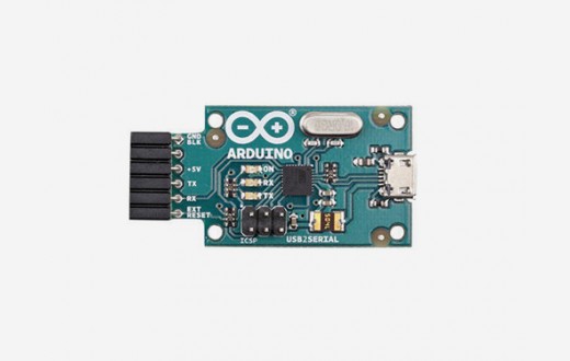
If you can make it out, that converter actually has the ATmega16U2 on it, so what we're basically doing here is still using the chip, but moving it off the Arduino so we don't have to power it when we're not programming the Arduino.
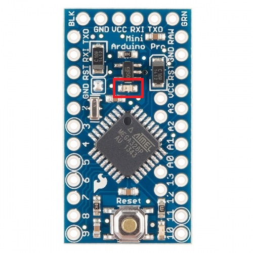
Here, I'll be using the 3.3V/8MHz Arduino Pro Mini. I'm using it partly because it will naturally use less power running at 3.3 rather than 5V, and IIRC, the 8MHz variation will use less power than the 16MHz.
Now I need to say a little about how this is gonna work. We're going to do two types of things to decrease the power consumption: physical, and programming. We've already mentioned one of the physical things (the choice of Arduino), but we'll also be changing options of the Arduino internally so that it essentially goes into a low power mode. I'll get to that more later, but I bring it up now because when you run it in low power mode, it sleeps for some percent of the time, and then briefly wakes up to do something, and then goes back to sleep. So we'll want to know how much power (everything else being equal) is being used in both its awake and asleep states.
To do this, the test program I'm running is a slightly modified Blink, the "Hello World" of Arduinos:
void setup() {
// initialize digital pin LED_BUILTIN as an output.
pinMode(LED_BUILTIN, OUTPUT);
}// the loop function runs over and over again forever
void loop() {
digitalWrite(LED_BUILTIN, HIGH); // turn the LED on (HIGH is the voltage level)
delay(4000); // wait for a second
digitalWrite(LED_BUILTIN, LOW); // turn the LED off by making the voltage LOW
delay(4000); // wait for a second
}
So this will just turn the on-board LED on for 4 seconds, then turn it off, and repeat. We're not messing around with any sleep modes yet, this is just to get a baseline reading. To test the power, we unplug the USB/serial converter from the Arduino, so we're only powering it from my breadboard 3.3V regulator, and then put my Digital multimeter (DMM) in between the +3.3V power supply and the Arduino power, so all power being used has to go through it. So...
5.3 mA with the LED off, 6.7 mA with the LED on. Apparently the LED uses about 1.3mA itself (for my actual application, I won't have an LED, but it's good to know), but there's a baseline of 5.3mA.
Now I'm going to upload an example sleep sketch I found here, where he explains it in far more detail than I do. The important part for these next few steps are that there are different "levels" of sleep mode, where more or fewer things get disabled in the sleep mode. We'll apply them one at a time here.
Now we're cookin. There will be 4 states here, LED on/off crossed with sleep/awake (the LED stays on if it went into sleep mode with it on). Results:
LED on:
Awake: 6.7 mA
Asleep: 3.8 mA
LED off:
Awake: 5.3 mA
Asleep: 2.4 mA
So we can see that putting it to sleep saves it about 2.9 mA, with the LED either on or off, and the LED takes about 1.4 mA, in sleep or awake.
Now, the next level, using the Watchdog timer sketch from here.
Same deal:
LED on:
Awake: 6.7 mA
Asleep: 3.5 mA
LED off:
Awake: 5.3 mA
Asleep: 2.1 mA
So it's pretty much the same as before, but it's saving an extra 0.3 mA when asleep.
Now... even with the Pro Mini I'm using, there's still a little on-board LED (not the one you can control) that's always on, when it's powered. But we know that the LED we're blinking is taking ~1.4mA... so what if we got rid of this other one?
This is a pretty common tactic, as seen here, for example. Grab a pair of pliers (or desolder it, if you're fancy), and rip that sucka out:
Now...
LED on:
Awake: 5.1 mA
Asleep: 1.9 mA
LED off:
Awake: 3.7 mA
Asleep: 0.53 mA
Nooice. This is getting good. Down to ~500uA.
I read on a number of sites that getting rid of the regulator can save even more power. Initially, this seems a little weird because I'm not actually using the regulator; I'm powering it directly to VCC with 3.3V. But I guess it's not surprising; we're talking about such tiny amounts of current here that maybe even backwards leakage current, or something, matters now.
Same as the LED, we physically remove it off the board (probably best to desolder this one...):
Without the regulator:
LED on:
Awake: 5.08 mA
Asleep: 1.87 mA
LED off:
Awake: 3.7 mA
Asleep: 0.48 mA
Hmmm, nothing incredibly mindblowing...
D'oh! I checked the code from that guy's page, and he was using the sleep setting SLEEP_MODE_PWR_SAVE, which is actually only the middle out of 5 in terms of power savings. Let's get crazy. Let's try SLEEP_MODE_PWR_DOWN, the lowest... is such a thing possible?
LED on:
Awake: 5.08 mA
Asleep: 1.49 mA
LED off:
Awake: 3.68 mA
Asleep: 0.10 mA
Oh god yes. That apparently saved us another 0.38 mA or so. Honestly, at this point, I have to start suspecting that my DMM may not be accurate enough.
A bit more Googlin' led me to find that I should be also disabling the ADC, which apparently the sketch above didn't. This was a little confusing to me because I had seen this list on several sites, outlining the different power saving modes:
- SLEEP_MODE_IDLE - the least power savings
- SLEEP_MODE_ADC
- SLEEP_MODE_PWR_SAVE
- SLEEP_MODE_STANDBY
- SLEEP_MODE_PWR_DOWN - the most power savings
And, if SLEEP_MODE_PWR_DOWN saves more than SLEEP_MODE_ADC (which I assume disables the ADC...), then I would also assume that SLEEP_MODE_PWR_DOWN would disable it too. Apparently not, as briefly mentioned here.
The relevant code snippet is
// Disable ADC, must be done before calling// power_all_disable() as to disable ADC,// clock is required// Refer to datasheet page 45ADCSRA &= ~(1 << ADEN);
Anyway, let's see what this does:
LED on:
Awake: 5.33 mA
Asleep: 1.54 mA
LED off:
Awake: 3.82 mA
Asleep: 0.01 mA
Hot. Damn. 10uA. That's less than some microelectronics devices I do research on use. It actually displays 0.02mA at first but then reliably drops to 0.01mA. I'm pretty sure the DMM's precision may actually be the bottleneck here, so I may bring this into work and use a precision electrometer.
Well, there you go. The ADC was using the last ~90uA. Strangely, all the other combinations above actually went up in current, strange...
Update: I brought it into work, here are the more accurate values:
LED on:
Awake: 5.1 mA
Asleep: 1.45 mA
LED off:
Awake: 3.82 mA
Asleep: 16.6 uA

At this point I'm pretty happy, though I will say that I'm still curious; some people online are reporting that they're getting down to about ~5uA, so I'm left wondering where that last ~10uA is going. Are they ripping out another component? Either way, this last 10uA is kind of pointless: almost no matter what I do, at this point, the "awake" state will consume so much more power that averaging over the brief time it's awake will mean this last 10uA is meaningless.