[latexpage]
Similar to...most of? my ideas, I don't remember why I thought of this. I think after I made the reinforcement learning robot, I was on a robot kick, and came up with this. Hexapods are of course a robot classic, but I don't think I had ever seen a centipede robot.
Why a centipede? Well... I can make up a few "practical" reasons: because of its length, it could potentially bridge gaps, or bend "upwards" to have height, or possibly even climb. But the real reason is because they haven't been done that much and I thought it would be cool, funny, and creepy.
There's a lot more to do, but here's where I am so far!
A typical arrangement you see with DIY/low budget hexapod legs is to have what I'm calling a "hip" servo, that rotates in the horizontal plane, and what I'm calling an "ankle" servo that rotates in the vertical plane, like this:
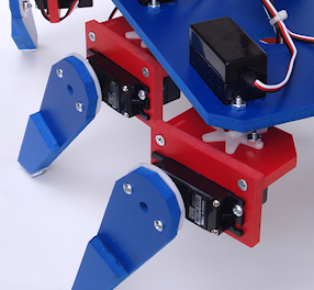
Together, these allow it to move left and right. There are actually lots of 3 servo designs, and sometimes the positions of which rotate in which directions are switched, but this is the main idea.
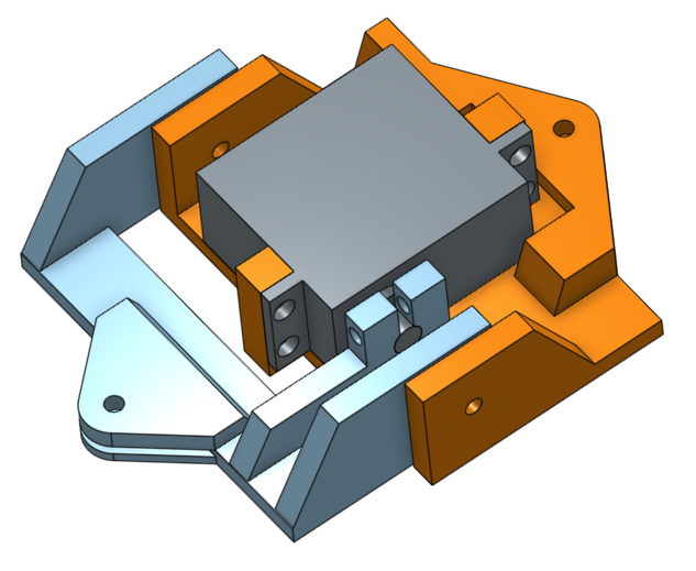
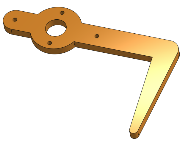
I was already worried about power requirements (more on that below), so I just went with a 2 servo design. I quickly whipped up a leg in Onshape:
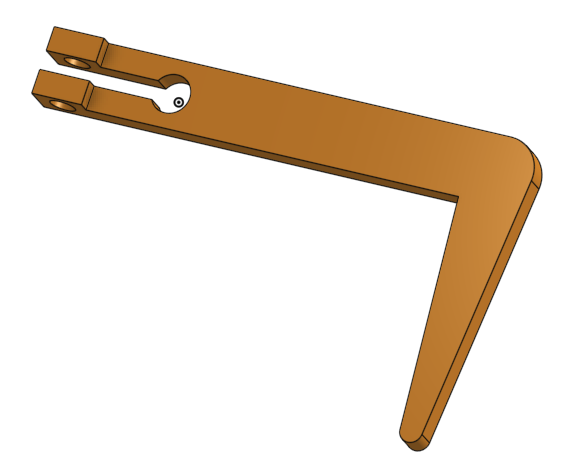
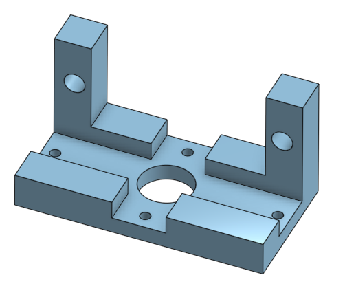
and then a "hip" connector:
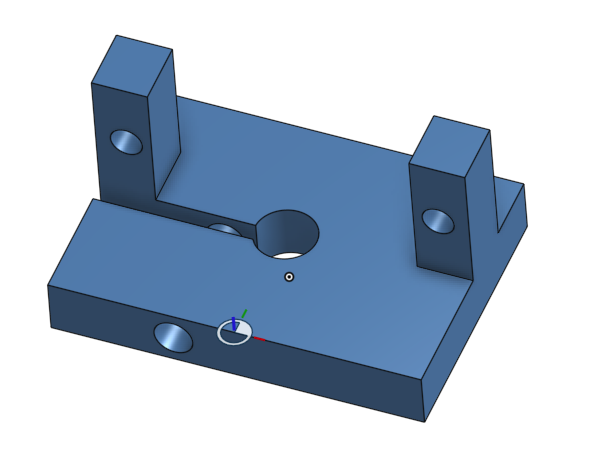
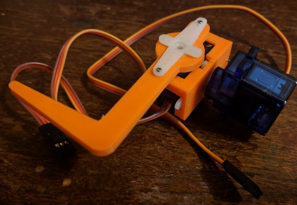
Together:
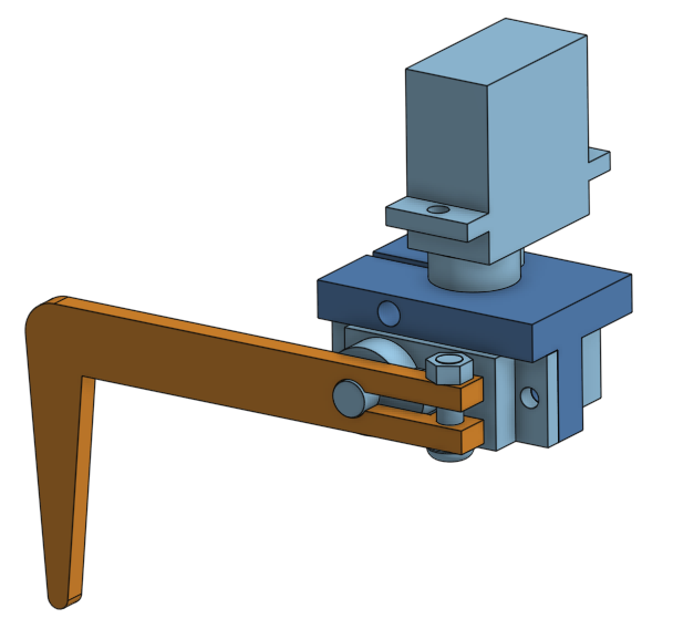
Here's it wriggling around:
If you've messed around with hobby servos at all, you've likely seen these, the classic SG90 servos. They're surprisingly strong for the dinky little things they are, but maybe I shouldn't be surprised: they can supposedly draw >700 mA of current when under high load!
All the servos here are controlled with the PCA9685 PWM breakout board. It's a pretty nifty thing, only a buck or two! It's an I2C device that allows you to simultaneously control up to 16 servos (or anything else that works with PWM).
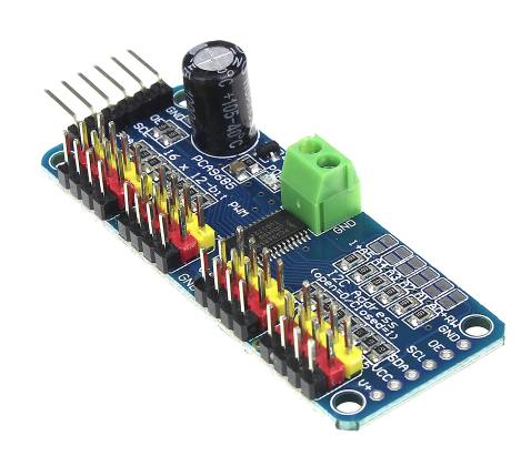
It has some other nice features, like that capacitor that smooths out voltage drops if you activate a bunch of servos at once. It also has holes for header pins at the other end, so you can easily daisy chain it with other I2C devices.
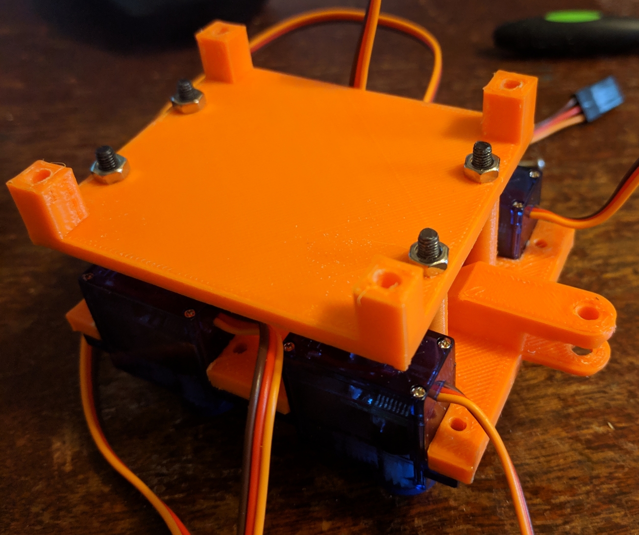
The next part to design was the main body segment. I thought about different aspects (how many legs per side, how to attach them, the size, etc) and it went through a few iterations, but here's the current one:
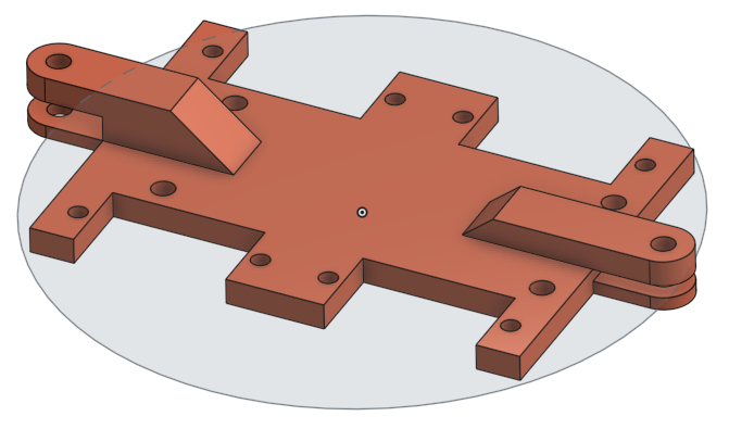
I might have made it a little bigger, to give the legs more space, but it's pretty limited by the Delta Mini's bed size (the circle there was a little smaller than that, so I could design around it). With the legs attached:
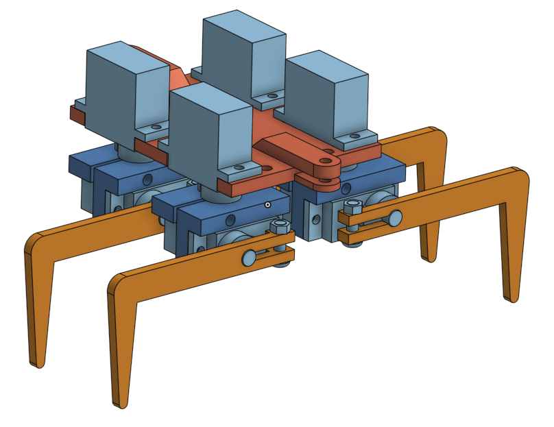
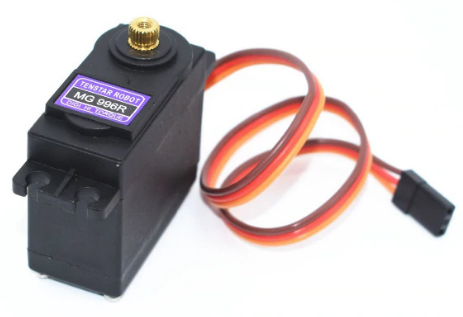
You might notice the overlapping ends. I wanted them to be able to connect head to tail with others and be able to "hinge". That much was easy with a first iteration, but I had other plans... I mentioned above that I wanted it to be able to bend upwards as well. To do this, I knew the lil SG90's wouldn't be strong enough, so I got the much beefier, metal geared MG 996R:
This thing is BEEFY. To test its lifting abilities, I designed this hinge system:
How does it work? BEEFILY.
Now you can hopefully see why I had to make those several layered hinges. These actually appear to be working pretty excellently, but I might have to consider reinforcing them with metal at some point.
So! Here it is so far:
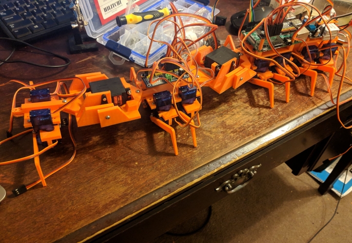
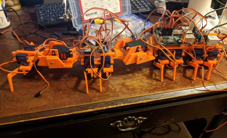
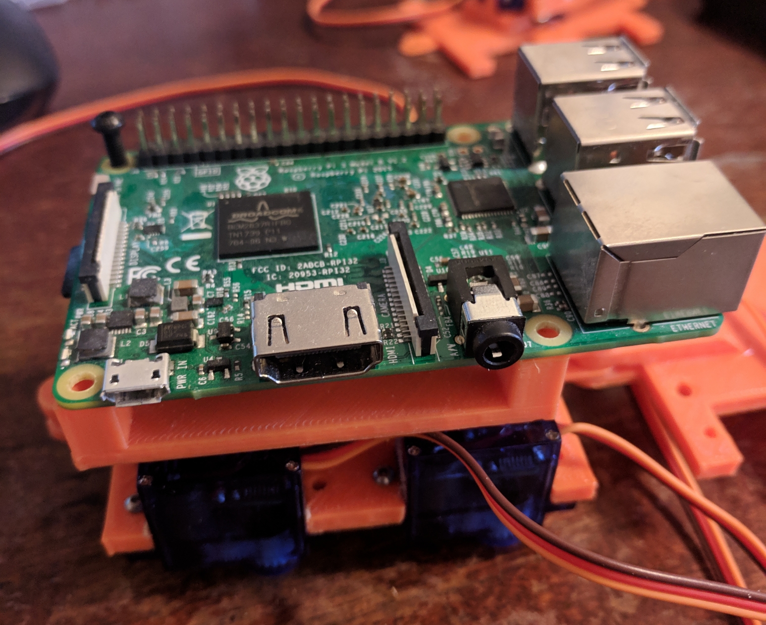
I also put holes in the body so I could place screws to act as standoffs for the different components. It's more crowded than I expected. It has to have (aside from the servos, on top): two PCA boards, a Raspberry Pi, a hefty regulator (for the servos), a small regulator (for the RPi), and a stack of LiPo batteries.
Now for the control code. I plan on trying different high level things with this (i.e., direct control, simpler control theory type things, and maybe even RL again), but here's the low level stuff so far.
I organized it in a hierarchical class structure that's worked really well so far. Just to be clear, it's not hierarchical in the sense of inheritance. Anything running with it needs a DriverBoard object, which is how it communicates with the PCA board. When you use more than 16 servos, you need to create multiple of these objects with different I2C addresses.
The most basic unit is the Servo class, which is passed a DriverBoard object and a board index (0-15). Using this, I can directly control a servo if I want. However, the next higher level class is Leg, which is also passed a DriverBoard object, a side (L or R, which side of the centipede it's on), and a leg_index (which runs 0-7). It then creates two Servo objects, one for the "hip" and one for the "ankle" I mentioned above, and assigns them the correct board index values based on its own leg_index (2*leg_index and 2*leg_index + 1). Similar idea for LegPair, which creates two Leg objects (L and R).
This allows me to pretty easily create a clean, understandable program at a high level. Here's an example:
b = DriverBoard(args.addr, 16)

if args.N_pairs > 4:
    b_front = DriverBoard(40, 8)

pairs = []
for i in range(args.N_pairs):
    if i < 4:
        lp = LegPair(b, i)
    else:
        lp = LegPair(b_front, i-4)

    pairs.append(lp)

start = time()
while True:
    for p in pairs:
        p.increment_ankles()
What does this do?
Neato!
There's actually a bit more. The part that's actually making them move there is the increment_ankles() function. To explain this, we have to go back to the Servo class. The main thing the servos will be doing is moving cyclically. To control a servo's position, you send it a PWM signal of a certain duty cycle. So, to make it to oscillate around a point, I found the PWM that corresponds to that point, mid_pwm, and define a pwm_amplitude that determines how far it goes above and below that mid point in its cycle. Then, making it move cyclically is just a matter of doing something like:
pwm = int(self.pwm_mid + pwm_amplitude*sin(self.phase + self.phase_offset))
And controlling phase however you'd like. Here's where the fun stuff comes in. To get a single leg to move in a "walking" pattern like you'd expect, the hip and ankle servos can't be doing exactly the same movement. To see what I mean, imagine parametrizing an $x$ and $y$ with a time $t$ and the sine function, to make a circle. If you do $x(t) = y(t) = sin(\omega t)$, you'll get something like:
Which obviously wouldn't make it walk. Rather, you have to give one of them a phase offset (like in the code above). To get a circle, $\pi/2$:
So, each servo has a phase_offset variable. However, the really cool thing about the hierarchical setup is that it lets this be set coherently too! Each Leg object knows its Servo objects need a certain phase offset with respect to each other. However, each Leg also has a phase offset with respect to the other legs! So a high level phase offset is given to each LegPair object, and then every class assigns the appropriate offsets to its lower level objects.
The above bouncing up and down example was pretty simple, but to do something more complicated, like...
It's also pretty simple!
b = DriverBoard(args.addr, 16)

if args.N_pairs > 4:
    b_front = DriverBoard(40, 8)

sleep(0.5)
pairs = []
for i in range(args.N_pairs):
    if i < 4:
        lp = LegPair(b, i)
    else:
        lp = LegPair(b_front, i-4)

    if i%2 == 1:
        lp.set_phase_offset(pi)
    pairs.append(lp)

start = time()
time_limit = args.runtime

while True:
    for p in pairs:
        p.increment()
Lastly, here's a couple practical hurdles, since it's good to show the action in the centipede-sausage factory a little.
I half suspected the hip/ankle to servo attachment would be a problem since the beginning, but I liked the clamping method and wanted to avoid the more "permanent" alternative. Servos are typically shipped with a set of horns you can screw onto the gear. Nicer ones (like the MG 996's) are ones you can unscrew/etc, but the SG90's are cheap enough that you're basically meant to screw them in and leave there I think.
So, after a while, I was finding that if too much torque was on a leg, the part where it attaches to the gear would just slip, which obviously can't work. So, I redesigned them to work with the servo horns:
The other hurdle was the power supply. To be honest, I'm still not sure what the answer here is, but I did figure it out. First, I had the Raspberry Pi and servos all powered from a buck converter that output 5V (and supposedly could supply 3A). When I was using fewer servos, this was definitely enough current for the Pi and servos, but I kept finding that the Pi would shut down. Of course this means it's getting underpowered, but it was never clear why. That part was easy to solve, just using a separate battery/regulator for the Pi.
The weirder thing came next. Sporadically, when doing a multi leg cycle test, it would work with 4 pairs, but if I upped it to 6 pairs, it would work for a second and then, I believe the technical term is "freak out". The legs would contort in these awful positions and just keep going in the direction they last went, as I frantically scrambled to cut the power.
From some reading, it seems like if servos get underpowered, their microcontrollers can reset and then they'll just keep doing the last command they were given or something. I'm not sure why, though. I was reading the current with a meter and it never went above 1.5A total. I tried upping the output of the regulator to be 6, 7V (because the servos can take that much and I thought maybe the voltage was dipping under high load). That didn't work.
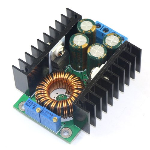
I thought that maybe, since my meter is just a derpy hobbyist one, it was having a really big load spike and I wasn't catching it. So, I bought this beefy boy, which is supposedly capable of 20A, 100W:
And... it still failed! Then, one time, I tried it without using the meter in current mode (I think I was monitoring the voltage instead), and...it worked! So it seems like having the meter in series was the culprit. I don't know enough about meters to know why, but dang that's annoying.
This is the first part, but there's lots more to do! A few off the top of my head:
- Integrate the bends, maybe even get it to climb a slight vertical
- Put a Raspberry Pi camera on it
- Make it autonomous?
- And much more!